
The Challenge
The SAE AeroConnect Challenge is a design challenge for University students to think about emerging UAV technologies and real-world applications. This year’s challenge revolves around designing an eVTOL UAM to rapidly transport passengers around the LAX airport.
Our aim is to develop a novel urban air mobility system to provide rapid passenger transportation around the Los Angeles airport area.
Here are the main design objectives to guide our design:
1. Safety
The system will be built with minimum triplex redundancy to ensure no single failure will cause loss-of-mission, and no dual failure will cause a loss-of-aircraft
2. Reliability and Throughput
The system must have a reliable battery system to support fast charging and extended service hours.
3. Comfort
The aircraft’s interior will be designed to maximize customers’ comfort while ensuring safety. The interior will have HVAC for climate control, and the seats will be designed to accommodate heavy luggage.
Some additional requirements include making the aircraft carbon neutral, reducing noise, and being FAA certifiable.
Our Solution – Summary
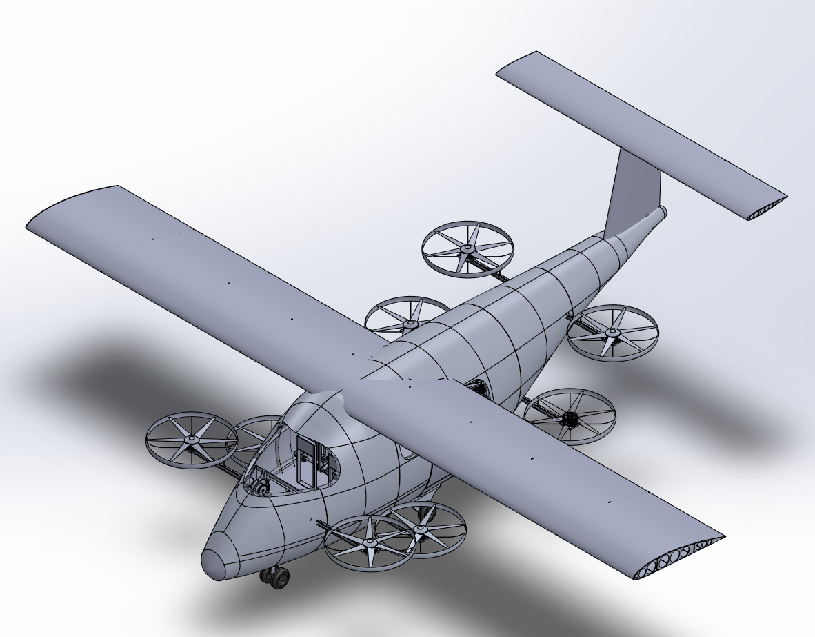
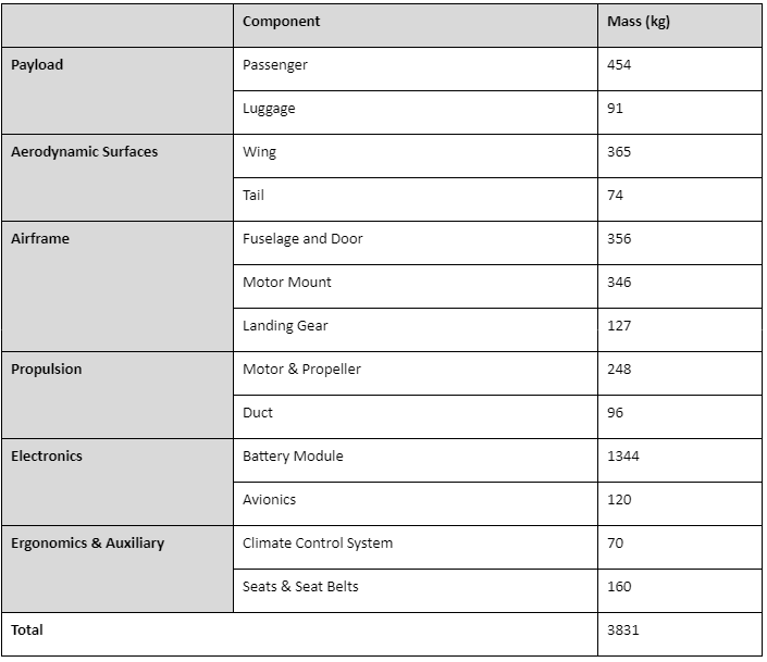
Our UAM is designed to carry four passengers with their heavy luggage. The propulsion system is chosen to maximize the power efficiency to travel at a steady 150 kph at cruise speed. The battery system can support fast charging (10 minutes) and long service time (around 4 hours) of the UAM. Additionally, it will be capable of autonomous operation, object detection, and avoidance.
Mechanical System
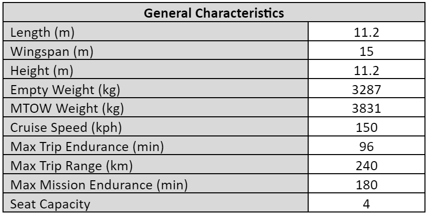
Vehicle Specification Summary
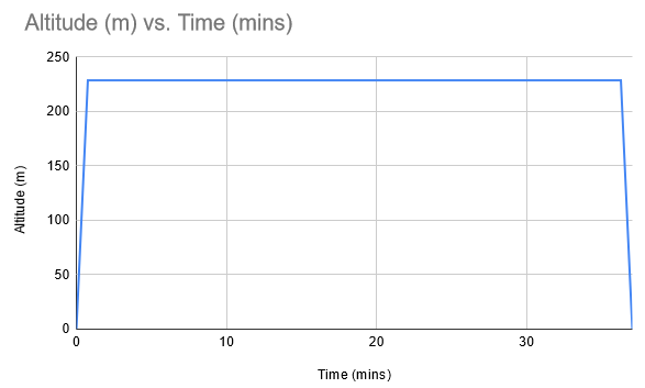
Flight Profile
Fuselage
The fuselage was designed to seat four passengers and their luggage with a comfortable and spacious seating arrangement, and the seats are also foldable to accommodate wheelchairs or strollers. The seats are configured and spaced in such a way that the passengers do not need to shuffle through aisles or move past each other to get out which allows for quick and efficient loading and unloading, which is also beneficial for emergency situations.


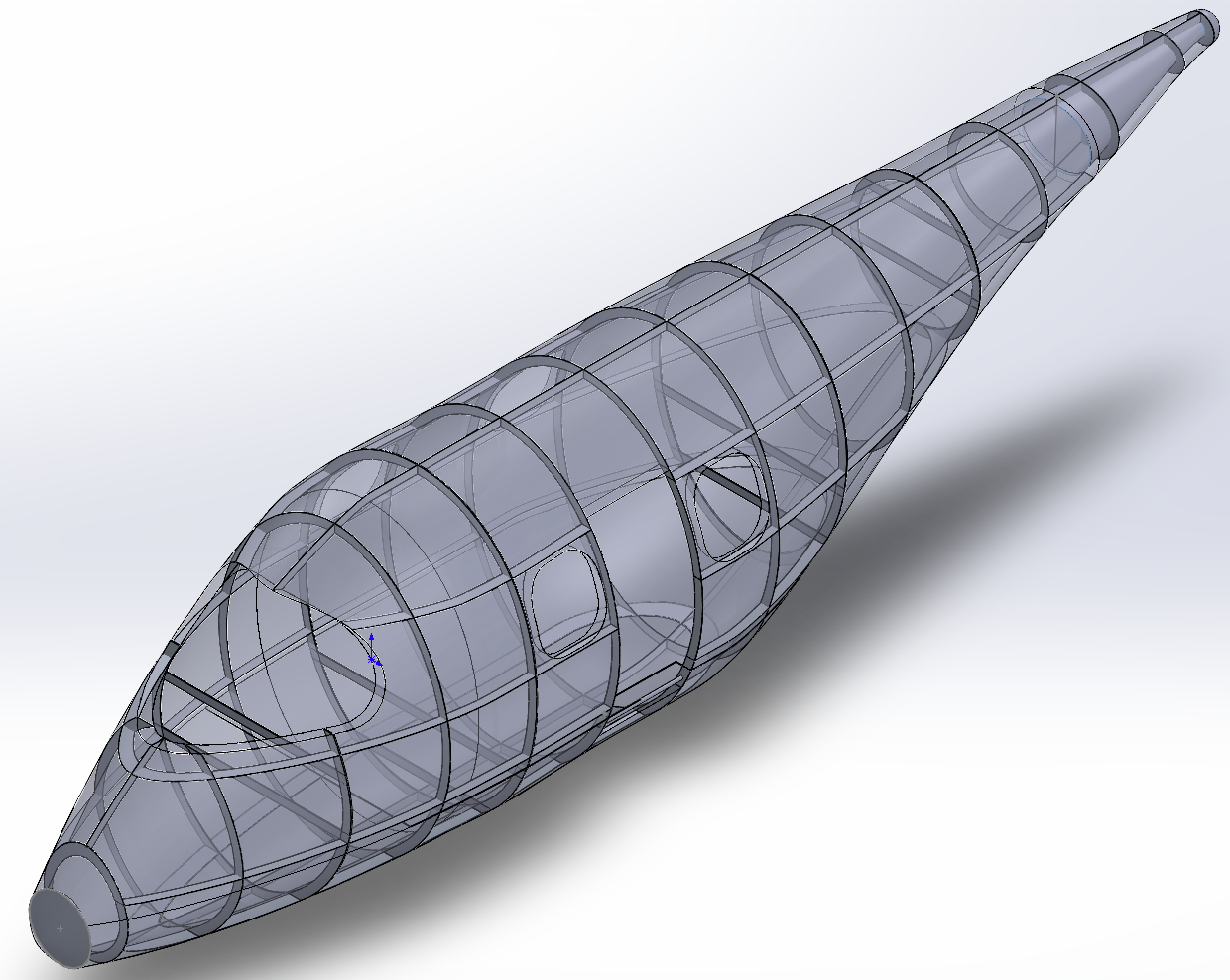
Structural Design
The fuselage was designed as a semi-monocoque structure, with frames and stringers lining the interior as shown below. It’s designed this way so that stresses are funneled into the stiffer material, as in the frames and stringers, allowing for the shell to be extremely thin and overall reducing the weight of the fuselage.
A box beam design was used for the wing structure, with an I shaped beam for the main spar and a flat beam for the rear spar. The spars carry most of the torsional load and there are additional stringers on the outboard half of the wings to transfer compressive forces onto the bulkheads. Aluminum 7075-T6 is used for the bulkheads, stringers, and spars and Aluminium 2024-T3 is used for the skin. The wing will be connected to the fuselage through the spars that will intersect and be joined to the fuselage ribs, and also main and supporting lugs on the underside of the wing so that also helps with integration.

Two FEA studies were conducted on the fuselage and wing structure using Femap and Nastran to optimize their strength to weight ratios. Each component was optimized to have a minimum factor of safety of 1.5.


We can see in the results that all the stresses are funneled into the structures rather than the shells because they are stiffer, allowing for the shells to be as thin as possible to reduce weight.
A CFD study was conducted on the ducted propellers using Solidworks Flow Simulation to ensure the UAM meets the sound requirement of 70dB at 500ft. The final optimized propulsion system was able to achieve a maximum acoustic power level of 68.58dB, well under the required 77dB.

Propulsion System
The propulsion system consists of 8 rotors powered by a single battery bank. The motor we selected is the EMRAX 268 high voltage axial flux motor capable of producing 53kW continuously with 93% efficiency at cruise RPM
The tilting mechanism is composed of aluminum 7075 and supports the propeller and motor using an I-beam capable of supporting 1.25G of acceleration to a factor of safety of 2.25 which is the acceleration the UAM is designed to operate at during takeoff and other flight stages. It is mounted to the stiff frames of the fuselage and driven by an AC motor and worm gear to allow for a low torque motor to be able to rotate the system and prevent it from being backdriven.
For the battery, we selected the 18650 NMC lithium-ion cell due to their cheaper cost and high energy density. This battery system can complete 4 full trips of maximum 50 nautical miles in a 3 hour mission time, including 4 10 min charging times and 300ft ground coasting at the start and ends of missions.
Weight Allocation
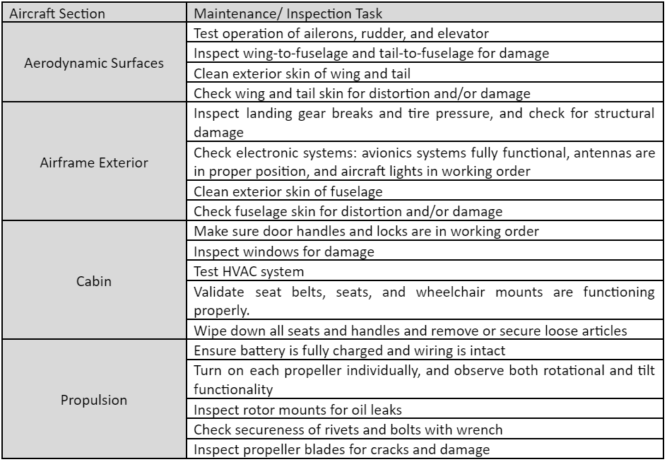
Maintenance
Since the UAM vehicles would operate almost continuously for 16 to 18-hour days, these aircraft will require daily inspections and periodic maintenance. Daily inspections should happen at a standard time of day, optimally before peak hours. Staff should be provided a checklist and training session on how to do the inspections
Electrical/Software System
Battery Management System (BMS)
The BMS monitors individual cell voltage, power draw, temperature, and state of charge. Then while charging, the BMS ensures all cells are evenly charged. We chose a modular BMS system that could scale to the size of our application. Lithium Balance’s modular BMS has one main board connected to many monitoring boards. If any monitoring boards detect a fault, the main board will disconnect the cells. This ensures bad cells are isolated and any single failure doesn’t result in failure of the system.

Passenger Comfort System
There is an HVAC system that will maintain cabin temperature and humidity along with ensuring the cabin air volume is exchanged quickly to maintain fresh air for the passengers. It also comes with air quality measurements that will alert the operators if there are any problems.
Failure Handling Module
The aircraft is equipped with a failure handling module that is capable of detecting and responding to any onboard failures. Failures are detected by sets of redundant identical sensors mounted on all flight-critical components as well as redundant sets of identical computers, including the flight controller. This allows for any failures to be detected as soon as they happen and also allows for the detection of sensor or computer faults. In the event of any failures, the flight computers will be notified and the autopilot will adjust accordingly. If the communications system is available, the ground station is alerted and can provide direction or assistance where necessary.
The Failure Detection Module also includes a Health Monitoring system that monitors all onboard systems and provides health measurements of components in order to prevent potential failures. This allows for preventative maintenance that can reduce incidents during a mission.
Autonomous Operation
The aircraft will operate entirely autonomously, with all required hardware onboard the aircraft. The ground station will provide destinations and routes to the aircraft, while being able to remotely monitor the vehicle. The aircraft will use ArduPilot, which is a well-established autopilot software used on many autonomous craft of varying size. It is an open-source software licensed under the GPLv3 licence and has been developed over many years by a devoted community. It includes integration with LiDAR modules and has implementations of object avoidance algorithms, which are used as part of the aircraft’s operation.
This is paired with Hemisphere’s Atlas GNSS Global Correction Service, which is a service that provides very high levels of geolocation accuracy. The tiered service provides up to 8-centimeter locational accuracy 95% of the time, allowing for autopilot navigation at very high levels of precision. The service requires minimal hardware to be mounted onboard the aircraft, and its satellite-based service delivery has coverage that entirely includes the operational area.
Object Avoidance:
The aircraft will autonomously avoid nearby obstacles using a combination of various sensors. This includes a Velodyne Ultra Puck LiDAR module detecting objects in a large radius within the horizontal plane. This is paired with Velodyne Velabit Solid State LiDAR modules mounted on the top and bottom of the aircraft, which provides object detection above and below. The large field of view for both the Ultra Puck and Velabit sensors provide full LiDAR sensing around the vehicle. The aircraft is also equipped with a radar altimeter, which is used in combination with the Velabit LiDAR to avoid collisions with terrain. The TCAS transponder onboard the aircraft also provides data about other nearby transponder equipped aircraft, which will be used by the onboard computer to avoid collisions.
The aircraft’s autopilot will use a combination of Bendy Ruler and Dijkstra’s pathfinding algorithms to avoid obstacles, with ArduPilot having built in implementations of these object avoidance algorithms.
Autonomous Takeaoff/Landing
The aircraft is capable of instrument only autonomous takeoff and landing. Prior to takeoff, the UAM will automatically detect if the passengers are properly seated and doors are all closed. The onboard LiDAR will detect obstructions around or above the aircraft.
The GNSS allows the aircraft to land accurately and precisely at the designated location. During landing, readings from the radar altimeter and LiDAR are combined to provide an accurate height above the ground. Before landing, the aircraft will hover above the landing zone, at a sufficient height to prevent the downdraft from injuring bystanders. The LiDAR will scan the landing zone for debris or bystanders. Once the area is clear, the aircraft will descend vertically.
All sensors needed for takeoff and landing are equipped on the aircraft, so no additional hardware is required to be installed at the landing site.
System Architecture

The software system responsible for managing all communication between customers, the ground station and aircraft is designed in a service-oriented architecture, with services deployed on a cloud platform like Microsoft Azure or Amazon Web Services. Customers will create service requests from their internet-enabled device, such as a smartphone or PC, with requests being stored in a queue within a cloud-based database. The ground dispatch center will coordinate aircraft routing based on customers requests, directing the aircraft to specified pickup and dropoff locations. This design is easily scalable and has redundancy by having multiple fallback cloud server instances, which will automatically be used should the primary server instance fail.
Communication System

The communication system consists of three different systems that have different responsibilities.
- The command and control link is the primary communication channel that connects the aircraft’s on-board computer and flight controller to the ground station. It transmits aircraft telemetry, health monitoring, mission updates, and emergency control. As a result, it needs to be extremely reliable and fast. This channel is the SATCOM and Cellular blocks on the diagram. The main connection is the satellite communication to provide beyond-line-of-sight operation to all UAM vehicles in the operating area. The backup system is a traditional cellular connection that would be available in most areas and at lower altitudes. We chose to use the Skytrac IMS-350 SATCOM system which conveniently also integrates a backup cellular connection and is specifically designed for unmanned aerial vehicle operation.
- The UAM ground station has a direct link to air traffic control and will implement any commands necessary. The UAM vehicle also has an air traffic control receiver on board as a backup.
- Traffic collision avoidance system or TCAS system integration. On-board the UAM vehicle is a TCAS transponder that is interfaced with by a TCAS computer unit that relays any traffic or resolution advisories to the flight controller to be handled automatically.
Participants: Kylie Berkshire, Cindy Chen, Ishtiaque Choudhury, Jared Crebo, Tanish Datta, Ahmed Elmenshawi, Tony Fang, Tejus Gangadharaiah, Wei Kang, Bryan Kwan, Zachary Lau, William Ledingham, Aaron Li, Chantelle Lin, Alexey Lyubavin, Huzaifa Malik, Adam Malsyzko, Shiropa Mazumder, Vedant Parekh, Dhruvi Patel, Myles Pribeg, Alexander Price, Fizza Rizwan, Tommy Tran, Charlie Zheng
Faculty Advisors: Dr. Chris Morton, Dr. Svetlana Yanushkevich