
The Challenge
The SAE AeroConnect Challenge is an engineering design competition for students that requires university teams to think about emerging technological challenges in the connected aircraft industry. This year’s challenge revolves around improving an existing mass transit system in a theme park in Orlando, Florida using the latest in Urban Air Mobility (UAM) technologies.
Our goal is to therefore develop a novel urban air mobility system to improve consumer transport in a theme park located in Orlando, FL.
The following six key missions requirements constitute the focus of our design:
- Safety
- Guest safety is paramount and as such, the system will be built with a minimum triplex redundancy so that no single failure will cause a loss-of-mission and no dual failure will cause a loss-of-aircraft.
- Reliability
- The system must support continuous operation from 8:00 AM to Midnight with regular maintenance considerations.
- Comfort
- The interior should be climate controlled, ventilated, and have seating and storage considerations in accordance with mass transit standards.
- Throughput
- The system must be able to support 3,000-5,000 daily users.
- Entertainment
- On-board park information and entertainment systems should be available to provide updates. The vehicles also include exterior themes to help represent the theme park.
- Technology
- The latest in autonomous transport technologies should be used including waypoint navigation, collision avoidance, and on-board wireless internet.
Additional requirements include making the system carbon neutral, reducing vehicle noise, and ensuring that the vehicles are FAA and SAE certifiable (FAA 14 CFR Part 25 and SAE Standard AS8037).
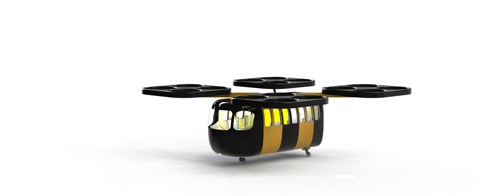
Our Solution – Summary
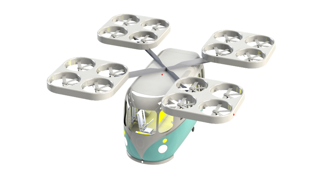
Our solution uses 70 electric UAM vehicles that can seat up to seven passengers (6 with 1 operator if required) including luggage. The vehicles are capable of autonomous flight with fully functional, real-time route optimization and collision avoidance modules. A mobile application was built to demonstrate the ease of access. Furthermore, 10 main ground stations with 3 landing areas provide quick passenger pick up and drop off hubs and allow for vehicle charging (96 minutes for a full charge).
Electrical/Software System
Route Planning and Optimization
Users will request rides between any two UAM stations using a mobile application. The backend will determine which vehicle should handle each request based on current location and vehicle utilization and is hosted with a managed Kubernetes services such as Google EKE or Amazon AKS for scalability and reliability. The mobile application allows for individuals to request to be picked up for a flight. The application will use location data from guests to provide estimated wait times, travel updates, and direct passengers to the nearest vehicle terminal where they can begin to board the aircraft of their choice. There will be iOS and Android support for the mobile application. A simplified demonstration video of a user requesting a ride through the application is shown below.
Optimizing the routes of the vehicle network boils down to solving a Capacitated Vehicle Routing Problem (CVRP) with pickups and deliveries. To solve the CVRP, the UAM system will utilize Google OR Tools. This route optimization software is given the coordinates of the travel nodes and planes in addition to the capacity and transport constraints. From here, it must calculate the distances between each node. Then, it searches for the optimal route that minimizes distance while satisfying the constrained transportation requests. It is also possible to add other constraints such as the remaining battery charge and flight time restrictions to the solver.
Mobile Application Demonstration
Autonomous Takeoff/Landing
The first stage of autonomous flight is ensuring the vehicles can complete autonomous takeoff and landings which may be crucial in the event of an emergency. Our main concern is passenger safety firstly ensuring the cabin door can completely close, passengers are safely seated and there are no other obstructions surrounding the vehicle. To overcome this danger the vehicle will have LZR-I30 safety sensors installed on the door to ensure there are no obstructions when closing. MK 14 series reed sensors will be installed into the passenger’s safety harnesses to ensure that every safety harness is fastened and finally the plane will utilize its 360-degree LiDAR to ensure the takeoff space is clear.
Secondly, we need to ensure that the vehicle can still obtain flight-critical information even when operating at low altitudes or with surrounding interference which may have an effect on sensor readings. To mitigate these dangers the plane will also utilize a radio altimeter and its lidar to provide more accurate readings when necessary. This sensor fusion will vastly reduce any uncertainty associated with any one sensor providing a more robust system.
Collision Avoidance
To operate multiple autonomous passenger-carrying aircraft safely and effectively within the same airspace a robust, redundant, and fault-tolerant collision avoidance system was developed. In our implementation, we use a combination of 360 LiDAR, ADS-B, GNSS/IRS, and a radio altimeter alongside a terrain database to provide both terrain and traffic avoidance. TCAS integration was foregone as the aircraft will be operating with its maximum altitude restricted to 120 meters above the ground and will not interact with other manned aircraft. The use of multiple types of sensors allows for the continued operation of the system, albeit with degraded capabilities, in the event of single or multiple individual failures. The collision avoidance module uses both Bendy Ruler and Djikstra’s pathfinding algorithms in conjunction to iteratively determine the safest path to its destination. A demonstration of the built module is shown below.
Collision Avoidance Software Demonstration
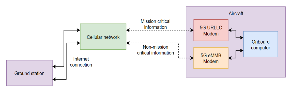
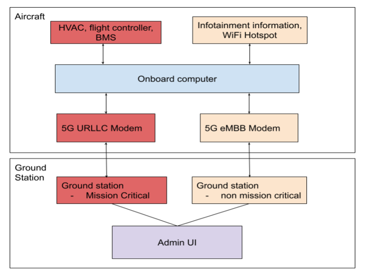
Communication System
The communication system onboard the aircraft will utilize two 5G cellular modems to interface between the aircraft and the ground station. The first modem will be for 5G URLLC communication, providing reliable and low latency communication for relaying important flight data to and from the ground station. The second modem will be for 5G eMBB communication, providing higher bandwidth service for the infotainment systems on board the aircraft.
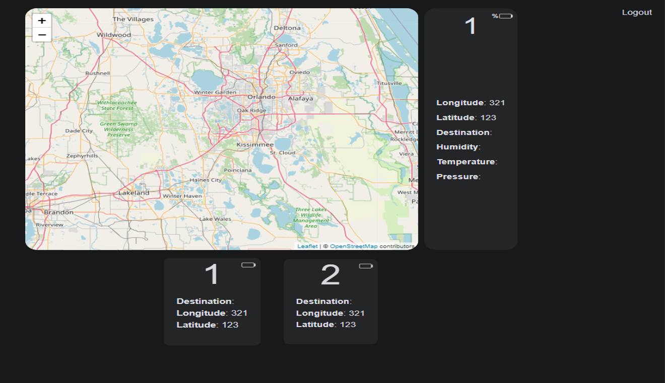
Administrative User Interface
The Administrative User Interface (Admin UI) is built with React to display each plane’s location and sensor data. The backend and authentication logic is implemented using Python Django. Once an administrator/operator logs into the system, they will have access to the plane’s data. The planes’ information is updated every minute and each plane’s location is displayed on a map, which is created using Leaflet JS. An example of the Admin UI is shown below.
Ground Station Overview
The ground station will utilize the admin UI to integrate flight information and communicate to the corresponding aircraft through 5G URLLC. The on-board entertainment Wi-Fi will use 5G eMBB from the ground station, which will be made available to customers through hotspots.
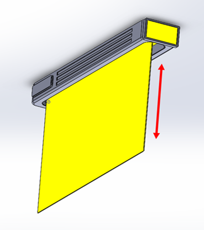
Infotainment System
An on-board information and entertainment system would provide audio and visual entertainment alongside wireless internet access. Individual tablets on each seat could be used as an input device to change the aircraft interior lighting and visual effects, the ambient music, flight information, and announcer language.
The main viewing screen is a double-sided 127 inch high-definition flexible OLED screen that can be automatically rolled up during boarding and disembarking for ease of access.
Heating, Ventilation, and Air Cooling (HVAC)
A conventional vapor cycle system using R134 refrigerant was used. This is commonly implemented in commercial vertical take-off and landing aircraft and HVAC pressure and temperature sensor data is sent to the ground stations for safe operation.
Battery Management System
Each UAM vehicle is equipped with a robust battery management system that will monitor the rechargeable battery to ensure it operates safely and efficiently. This includes detecting the overcharging of cells, current draw, battery temperature, and electrical isolation to the chassis. Once a fault is detected the battery management system will disconnect power as necessary and send an alert to the on-board computer which will be relayed to the ground control. The UAM vehicle will use the EVAL-L9963-MCU and smaller EVAL-L9963-NDS boards to manage all the cells in the rechargeable battery while providing additional safety and design redundancy.
Failure Detection and Health Monitoring Module
The failure handling module is designed to identify failures and mitigate them. Each UAM vehicle is completely autonomous and must ensure that the mission can be completed even after multiple failures within the aircraft. Therefore, the UAM vehicle is capable of detecting and autonomously preventing failures from affecting the completion of the mission. In the event of multiple critical failures, the UAM vehicle will identify each failure and adjust the mission as required.
The purpose of the Health Monitoring system is to track the status of crucial components on the UAM vehicle through sensors, allowing the system to quickly send alerts to the ground station at the onset of adverse events, such as abnormally high motor stator temperature.
Mechanical System
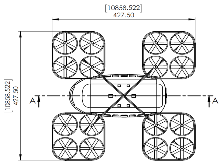
Vehicle Specification Summary
| Rotor Length/Span [m] | 10.9 |
| Empty Weight [kg] | 3245 |
| Payload Capacity [kg] | 726 |
| MTOW [kg] | 4000 |
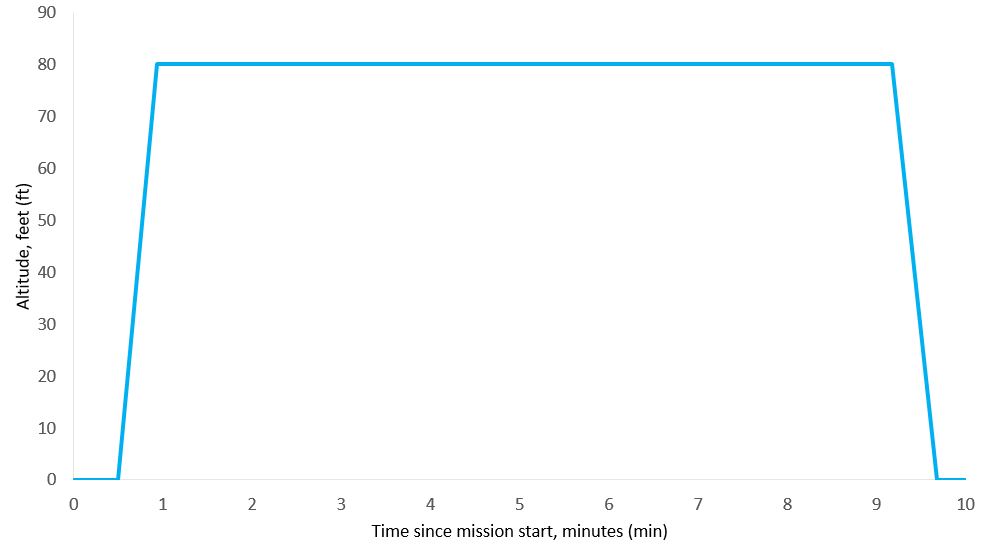
| Maximum Plane Endurance [hrs] | 0.4 |
| Operational Range [km] | 10 |
| Seating Capacity | 7 |
| Cruise Speed [km/h] | 100 |
| Maximum Ground Speed [km/h] | 150 |
| Operational Ceiling (AGL) [m] | 120 |
Flight Profile
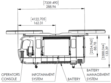
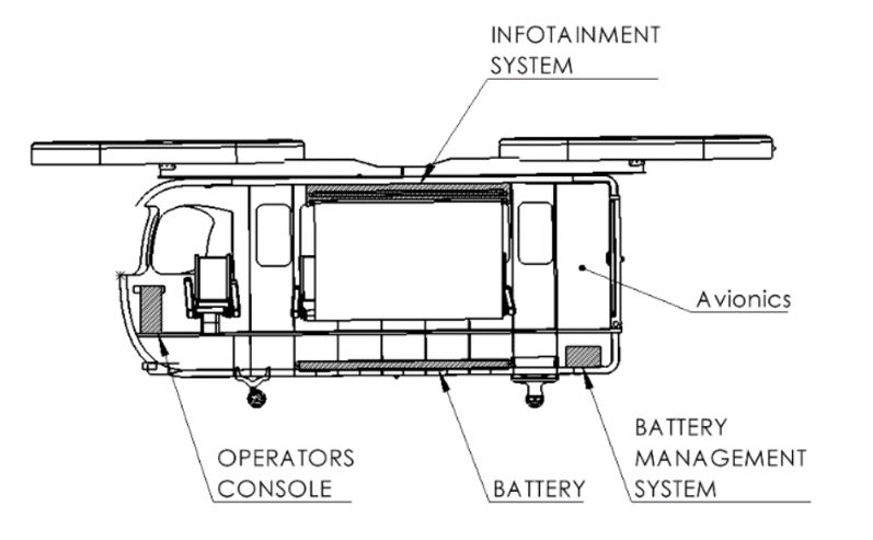
Fuselage Layout
The vehicle has seating for 7 passengers and up to 23 kg of luggage per person. The seats are placed around the walls of the fuselage, and in addition to the retractable central screen, maximizes movement space in the vehicle for quick loading and unloading. The front seat can be used by an operator with its own console if necessary. In a fixed-wing aircraft, loading has to be controlled to ensure the center of gravity does not exceed a certain limit. In a multi-rotor vehicle like this one, much larger changes can be tolerated. The many rotors on the aircraft can thus precisely counter a shifted center of gravity. A diagram of the layout is shown below.
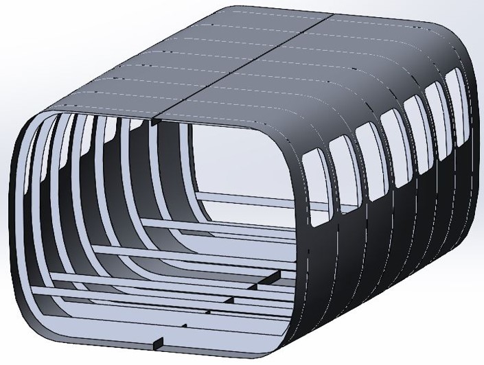
Structural Design and Simulation
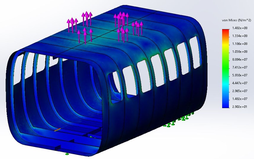
The fuselage has been designed to sustain 1.5G maneuvering loads and a lifetime of 65000 service hours or 131000 load cycles. The ultimate load condition is 2.25G. The analysis covered loading conditions as a result of propulsion lift and the normal force on the fuselage when on the ground. In-flight dynamic loads such as motor vibrations and flutter were not accounted for.
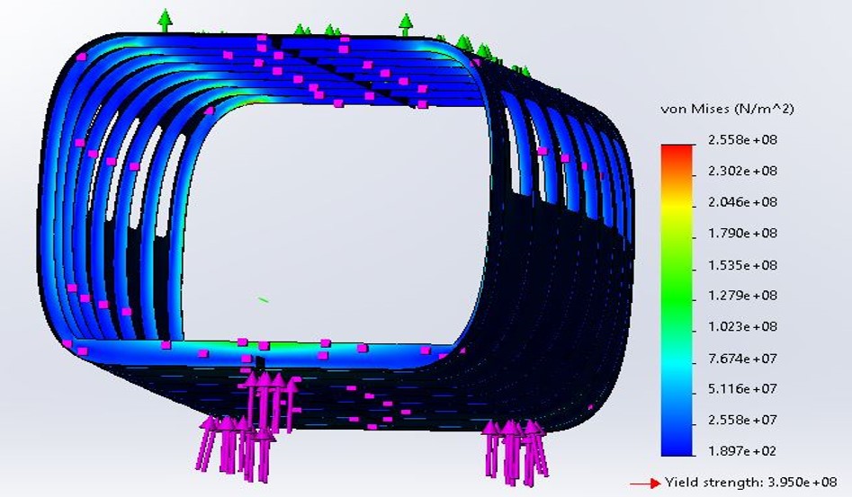
The fuselage is designed to use Aluminum 2024-T361, with the highest yield strength of the 2024 series of Aluminum. The semi-monocoque fuselage is supported by 8 ribs that are concentric and parallel to the shell of the fuselage. The first and second rib on either end is reinforced to support the fuselage when the vehicle is resting on the landing gear.
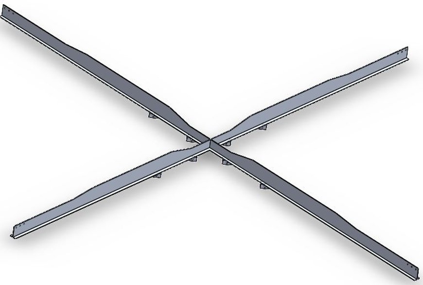
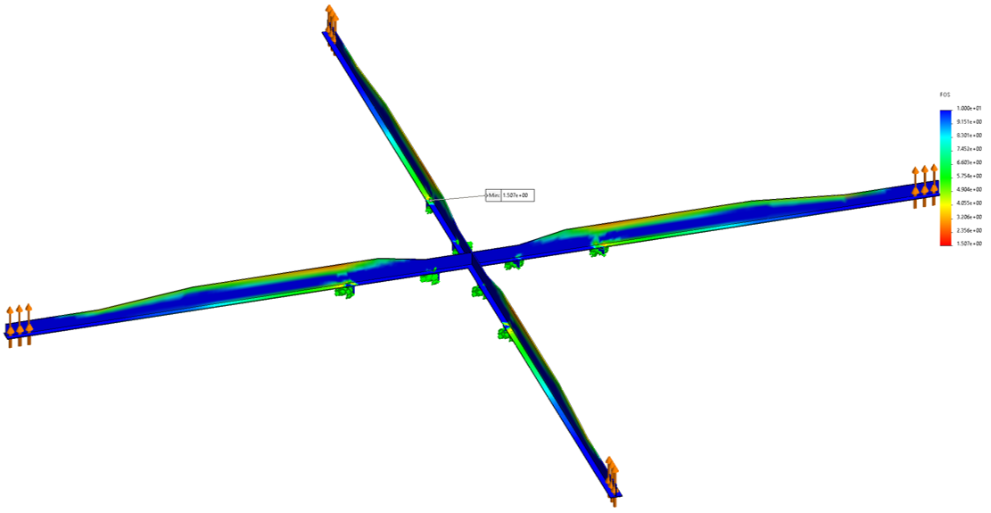
The motor mount is designed to use Aluminum 7075-T6. It is heavier than but has higher strength compared to aluminum 2024, which is needed for the most heavily loaded structural component.
The propulsion lift simulations were performed on SolidWorks and assumed that the lift was applied to 6 points on the top of the fuselage. A factor of safety of 2.3 was achieved for the propulsion lift.
The landing force simulations were directed at the locations of the tricycle landing gear on the bottom of the fuselage. A factor of safety of 1.5 was achieved for the landing gear.
The motor mount simulations assumed the propulsion forces occur at the end of each beam, with attachment to the fuselage in the center. A factor of safety of 1.5 was achieved for the motor mount. The fatigue life corresponding to the simulations is more than 10 million cycles which far exceeds the entirety of the vehicle service life.
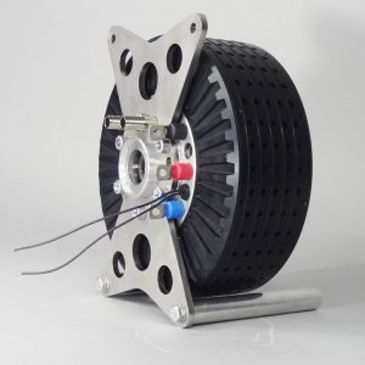
Propulsion System
An EMRAX 288 HV axial flux motor was selected. It provides 53 kW of power (109 kW peak) at 2200 RPM at up to 98% efficiency.
Each vehicle is powered by 18650 NMC lithium-ion batteries. There are 22701 Cells per battery bank which provides 210 kWh (up to 244 kWh) at 580 V. The design capacity of 210 kWh provides approximately 25 minutes of flight time at maximum load before recharging is required. A full recharge takes 96 minutes.
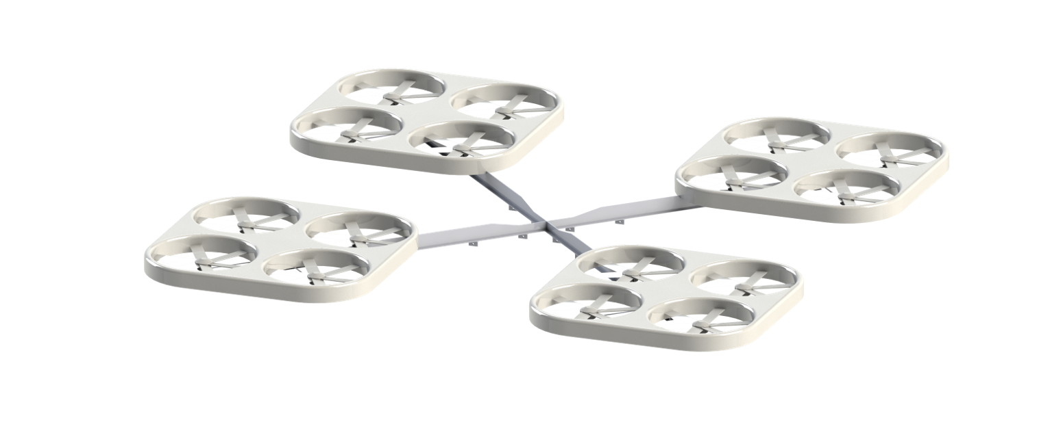
The vehicles also use 16 ducted fans arranged in groups of four. Using ducted fans provides noise reduction and improved efficiency compared to undusted configurations.
Weight Allocation
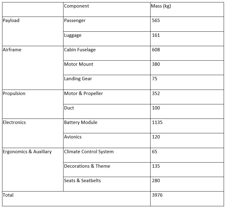
In the weight estimation, the passenger weights were based on the average American adult weighing 80.7 kg. Each passenger was allocated 23 kg for personal belongings, which is the standard luggage weight for North American airlines.
Safety and Regulatory Compliance
The multirotor design allows the vehicle to operate with up to 4 motor failures. A multirotor vehicle does not have the risk of falling under a stall speed or a VTOL transition phase. Limits on operating altitudes and speeds will keep the vehicle in a safe operating envelope. The vehicle will comply with FAA Aircraft and Rotorcraft Transport Category Airworthiness Standards. The vehicle features landing, navigation, and anti-collisions lights as per SAE Aircraft Lighting Standards. Furthermore, the vehicle can also be placed under the manual control of an operator if required.
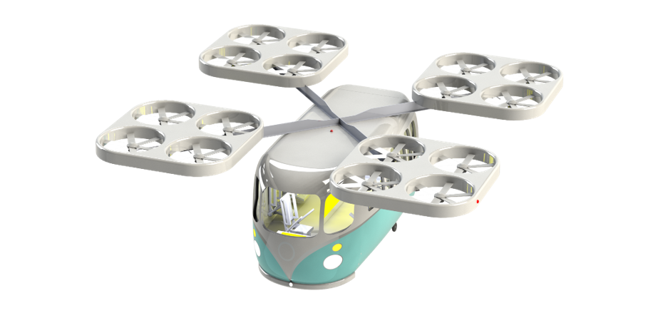
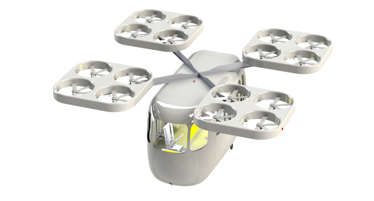
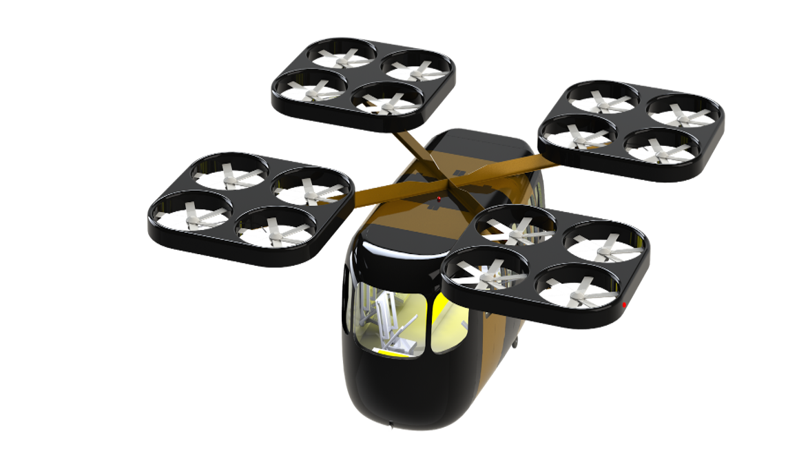
Exterior Themes
There are many different opportunities for vehicle aesthetics. Light-weight plastic components can be used as decorations or as shaping material on the exterior of the vehicle without significantly affecting vehicle performance. Exterior lighting can be easily added and connected to the vehicle’s electrical system. The flight analysis has accounted for an additional 35 kg of decorative components. Sample themes have been provided below.
Ground Station Services
Vehicles will land at ground stations for passengers to board and deboard. Each station will have three landing pads, associated recharging stations, and a 5G communications terminal with URLLC and eMMB technology.
Maintenance hangers will handle storage and heavy maintenance of the vehicles, with a capacity of 10 vehicles per hanger. Hangers will be placed strategically throughout the theme park to minimize transfer distances to ground stations. Unmanned ground vehicles (UGV) will be used to tow the UAMs between ground stations and the maintenance hangers. The UGVs attach to the aircraft’s nose landing gear and are remotely controlled.
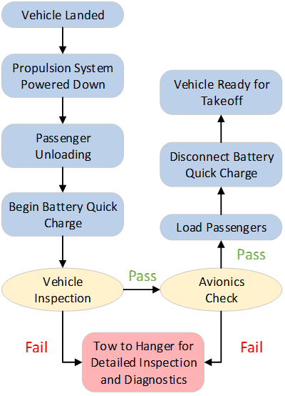
Maintenance
The vehicles are expected to operate 16–18-hour days, and therefore require daily inspections. Daily inspections, along with pre-flight inspections by a station attendant, will be carried out at the ground stations. Small easily replaceable components will be available at the ground stations in case of failures. Heavier maintenance will be performed at the maintenance hangers. The hangers will also have spare vehicles on hand to switch off with vehicles that require servicing. A maintenance workflow chart is shown below.
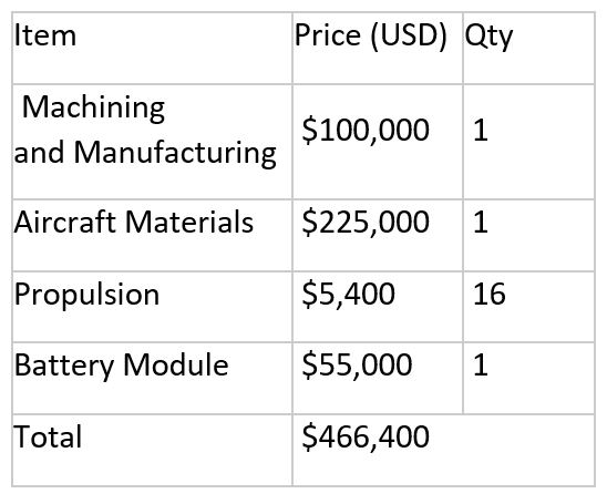
Cost Estimation
A rough material FOB cost has been provided for a single airframe. Labor, logistics, ergonomics items, and auxiliary item costs were excluded from this estimate. The battery module will also be a wear item as the maximum capacity will degrade over time. Replacements will be needed over the lifetime of the airframe to maintain the required flight time.
Contributors: R. Ahmed, G. Benson, C. Chen, J. Crebo, A.T. Demong, T. Fang, T. Gangadharaiah, J. Gobeil, E. Ho, K. Jeon, W. Kang, S. N. Kiani, B. Kwan, E. Lam, Z. Lau, W. Ledingham, A. Li, E. Lok, A. Ong, M. Pribeg, A. Price, S. Regmi, S. Sajid, P. Shmerko, T. Tran, E. Truong, T. Yang, C. Zheng
Faculty Advisors: Dr. Chris Morton, Dr. Svetlana Yanushkevich